Mar 2016
surface reconstruction from point clouds


 Around Congress ave in Austin, TX
LiDAR Processing Experiments
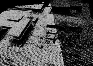
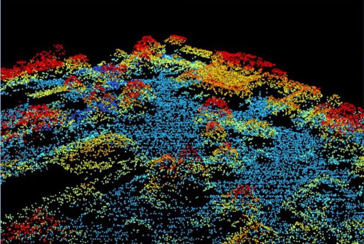
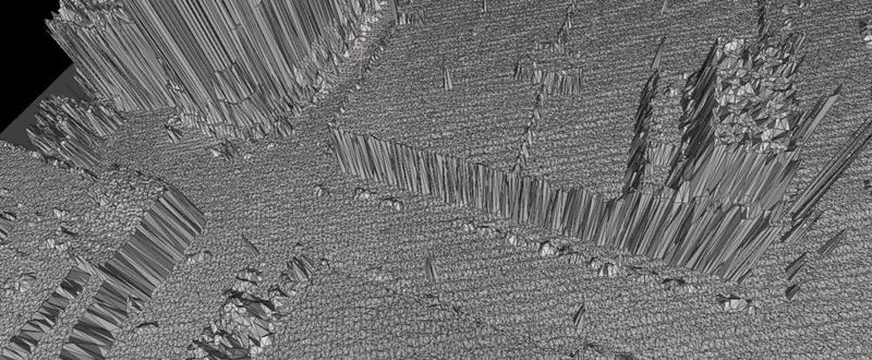
Early 2016 I bought a LiDAR scan of all of Travis county! This seemed super cool, but visualizing it was hard since the only option is really just to color code based on elevation, because there’s no information about surfaces. You could do some whack normal calculations based on neighboring points, but check out how erratic this sampling pattern is.
Why are the points so close together? Was there an error in the processing? Why is there a little hole over there? Nobody knows. I need a technique that can handle this non-uniform sampling pattern.
 Is this the best we can do???
No! Let’s do some 3D reconstruction.
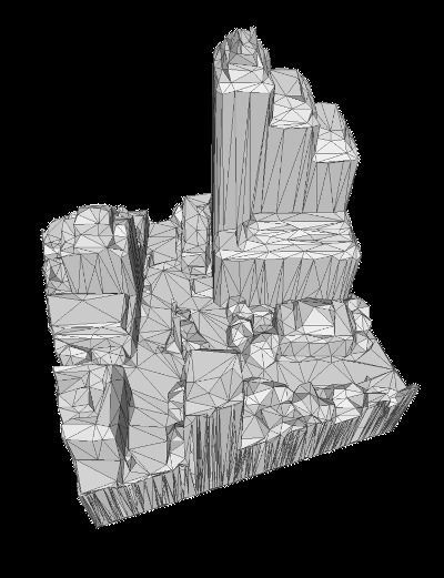
3D Delaunay triangulation
This is the most obvious thing to do, but the results weren’t that great. And the elevation changes were so much bigger than the ground plane changes that I had to project all the points on the ground, do the triangulation in 2d, and then extend the point back up into the z dimension. So the results were super noisy because of this technique:

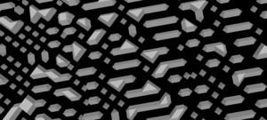
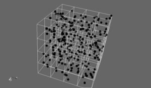
Volumetric Grid sampling
Volumetric reconstruction techniques are very common because of the parallel nature of the processing and the simple algorithms. The downside is that you are storing data for the whole grid, which goes up cubically in the resolution of the reconstruction, limiting the size. Still, I don’t really care because this is an offline algorithm and I can process the data in tiles. Probably the most famous technique for this is Kinect Fusion.


So I make 500x500x500 voxel cube array, and then partition the LiDAR points into chunks that are more or less 500x500 points. The goal is to sample the point cloud at as close to the same frequency as the LiDAR scan as possible so we don’t lose any information, but still have enough to extract a surface from the volume. In the images above, the grid resolution was too small, so you can get volume cells that are empty, even on a surface!
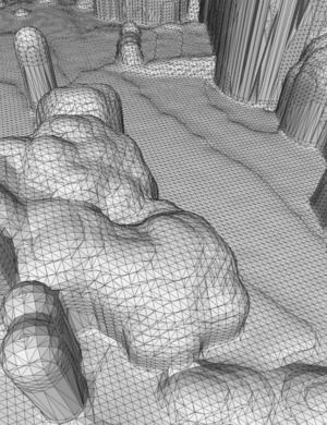
I didn’t make a visualizer for the volume directly, since I knew I wanted to make a mesh anyways. I could do some cool parallel GPU ray marching but Marching Cubes is really fast so I just found some code to do that. At first the results weren’t great but that brings us to
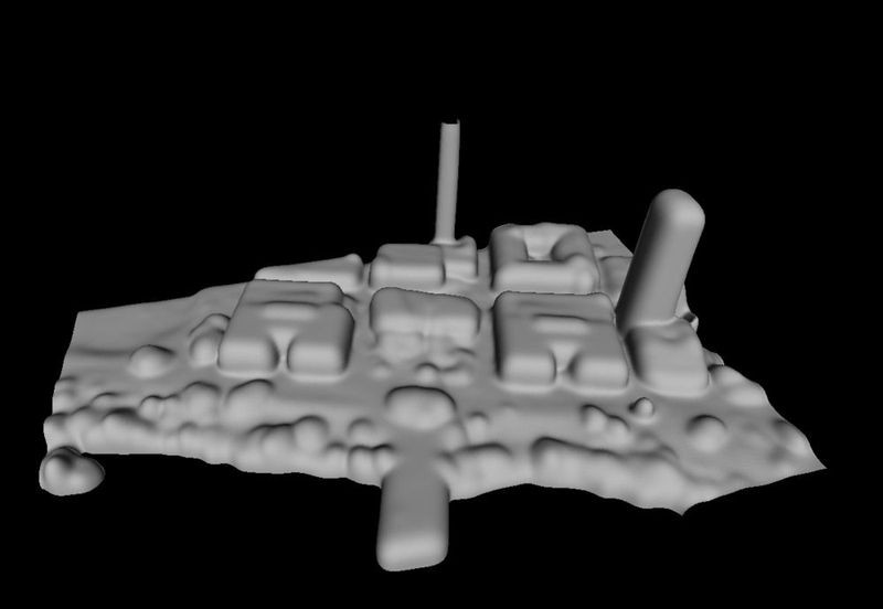
3D Volume Filtering

I was getting a lot of noise in the data, with some gaps in between points or spurious readings around in the air. So I wanted to run a low-pass filter on the volume. This is equivalent to blurring an image in 2D, but instead I’m blurring the “density” values in the volume in 3D. I started with a box filter but that made everything look really blocky. Ideally I want to do a gaussian. And, since the Gaussian Blur is separable, so I can run 3 1-dimensional blurs, with precomputed gaussian weights. I used a 5 tap blur.
I also changed the point integration so that, for a given Lidar point, instead of just increasing the density of the cell it falls in to, it will increase the density of every cell beneath that cell. This assumes that every point is a
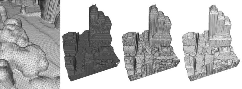
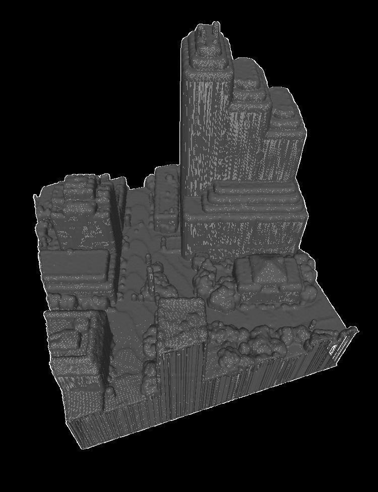
Decimation

So now I have this super high quality mesh but I’ve processed one city block and I have 60 million triangles or something stupid. See above, the marching cube output has a point one the corner of every volume cell. So I need to simplify the mesh with quadric edge-collapse decimation. This is named after the super brutal military discipline used in the Roman Army. The mesh processing is pretty brutal too. Except, I must be doing something wrong in Meshlab, or Meshlab kind of sucks. Don’t get me wrong, I love Meshlab. But half of the tools don’t work out of the box. I ended up using OpenMesh to do the decimation, using a Cinder app, and using their command line sample. I suspect this can be slightly improved by tweaking but I got great results out of the box.
 COM ON MESHLAB, YOU CALL THAT DECIMATION? MORE LIKE MASHED POTATOES
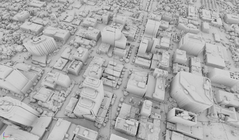
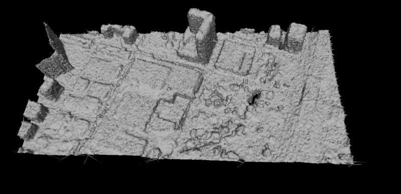
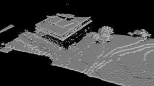
Rendering
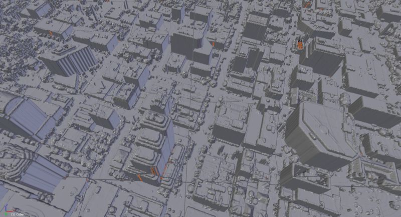
So we have a reasonably sized mesh, where we can load the whole thing into GPU memory and get a realtime frame rate. I’ve always loved the visual from a good Ambient Occlusion effect, because it gives you a tremendous amount of spatial perception that you don’t get with simple surface normal shading. Especially with cityscapes, this is really useful to make out small details. Similar to the way shadows work, our brains have been trained to process these subtle lighting cues to infer 3D structure. Just look at the difference! (using Blender)


In the future, I want to make a custom ambient occlusion implementation to make some really nice renders. Something like this genius technique described by Evan Wallace here. But first, I have to figure out how to parameterize the surface to build a texture map - and make sure the the sides of buildings have enough space in the map to get a shadow gradient up the side.
Future Work
-
There’s still some obvious ugly grid lines as an artifact from my tile generation. I should clean the surface generation up and get the tiles to have the same vertices on edges so I can merge them.
-
Parametric box fitting! (to the volume or the point set) this could greatly compress the mesh, and allow me to classify points as trees or buildings! then do other cool stuff?
-
Custom ambient occlusion rendering
-
Convert the rest of the scan!
-
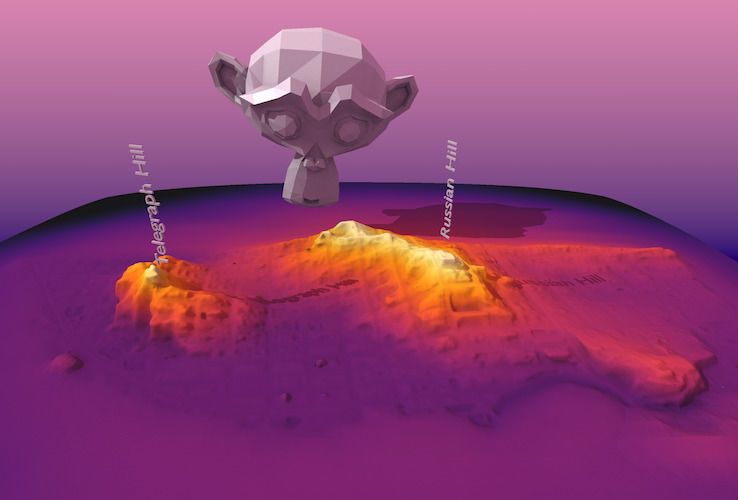
I downloaded a GeoTiff of LiDAR scan of downtown San Francisco - GeoTiff are way easier to process into a mesh, because they already have a regular grid and you basically just have to create two triangles for each pixel connecting the neighbors, and set each point to the value of the pixel. No volumes necessary. But i’d like to do create visualizations of a lot of different cities.
-
Time comparison - Austin is growing super fast and this scan is already 5 years out of date. Now, where could I get an updated scan data… Google maps? Apple Maps? Going to try using a GLTrace to rip out the vertex positions… is that allowed?